Chapter 5. 5G Radio Technologies

Updated: 2 days ago


Figure 5.0: Chapter opening. Numerology, massive MIMO and beamforming.
5.1 Why This Chapter Follows the Split

Figure 5.1: The six building blocks of this chapter.
What you will be able to explain by the end
What OFDM does in New Radio, and how much of it you already know from LTE.
How numerology works, and why doubling the spacing halves the slot.
The difference between massive MIMO and beamforming, which are routinely confused.
What bandwidth parts are for, and why RedCap devices depend on them.
Why carrier aggregation and dual connectivity are not the same mechanism.
Remember One sentence carries this chapter. Every parameter LTE fixed, New Radio made configurable. Everything else is a consequence of that. |
5.2 The New Radio Air Interface

Figure 5.2: OFDM, the resource grid, and the two frequency ranges.
Start with the reassuring part. New Radio uses OFDM, exactly as LTE did. Data is spread across many narrow subcarriers, each carrying a modest rate, which makes the signal robust against multipath.
Waveform choices in each direction
The downlink uses cyclic prefix OFDM. The uplink can use CP-OFDM as well, or DFT spread OFDM when the device needs better power amplifier efficiency, which matters most at the cell edge where transmit power is the limiting factor.
The resource grid
Everything is scheduled on a grid of time against frequency. The scheduler assigns rectangles of that grid to devices. The smallest unit is a resource element, one subcarrier during one OFDM symbol. Again, this is LTE thinking carried forward.
Two frequency ranges
Range | Spectrum | Character | Practical role |
FR1 | Sub 6 GHz | Good propagation, moderate bandwidth | The coverage and capacity workhorse |
FR2 | Millimetre wave | Enormous bandwidth, very short range | Hotspot capacity, depends on beamforming |
Did You Know? FR2 is not simply FR1 at a higher frequency. Path loss and blockage are so severe that a millimetre wave link is only viable because beamforming concentrates the energy. Remove the beamforming and the link does not exist. |
5.3 Numerology, the Choice LTE Never Offered

Figure 5.3: Four numerologies, and what each one costs.
This is the most important concept in the chapter. LTE fixed subcarrier spacing at fifteen kilohertz for every deployment. New Radio defines a family of numerologies indexed by mu, where the spacing equals fifteen kilohertz multiplied by two to the power mu.
Mu | Subcarrier spacing | Slot length | Typical use | Trade off |
0 | 15 kHz | 1 ms | FR1 coverage | Identical to LTE, best range |
1 | 30 kHz | 0.5 ms | FR1 mainstream | The common choice in deployment today |
2 | 60 kHz | 0.25 ms | FR1 and FR2 | Lower latency, reduced range |
3 | 120 kHz | 0.125 ms | FR2 millimetre wave | Very short slots, very short reach |
The mechanism behind low latency
Each step up doubles the subcarrier spacing and halves the slot length. A shorter slot means a transmission opportunity arrives sooner, which is precisely how URLLC meets the one millisecond budget discussed in Chapter 2. The latency improvement is not magic, it is arithmetic.
What it costs
Wider spacing means a proportionally shorter cyclic prefix, so the signal tolerates less delay spread. Less delay spread tolerance means less range and more sensitivity to multipath, which is why nobody simply configures the highest numerology everywhere.
Important Numerology is a planning decision, not a performance setting. It has to match the cell radius and the propagation environment, and getting it wrong shows up as unexplained coverage loss. |
5.4 Frame Structure and Flexible Scheduling

Figure 5.4: The frame is fixed. What happens inside it is not.
The outer structure deliberately did not change. A radio frame is ten milliseconds and contains ten subframes of one millisecond each, exactly as in LTE. That constancy keeps timing and LTE interworking manageable.
What changes with numerology is how many slots fit inside each subframe. At mu zero there is one slot per subframe, at mu one two, at mu two four, and at mu three eight. Each slot still carries fourteen OFDM symbols, so the slots simply get shorter as you climb.
Two mechanisms that go further
Mini slot scheduling, formally type B scheduling, lets a transmission start without waiting for a slot boundary. When you need the lowest possible latency, you do not wait for the next bus.
The flexible slot format lets symbols within a slot be designated downlink, uplink or flexible, so the direction adapts to demand rather than following a fixed pattern. This is a genuine departure from LTE time division duplex.
Key Takeaway Frame and subframe are constants you can rely on. Slots, and even parts of slots, are where 5G buys its latency. |
5.5 Massive MIMO

Figure 5.5: From one antenna to sixty four elements and beyond.
The word massive refers to the number of antenna elements, and the jump is larger than most people expect. Single input single output uses one antenna at each end. MIMO in LTE typically used two by two or four by four configurations to send multiple spatial streams to one user. Massive MIMO commonly means sixty four transmit and sixty four receive elements in mid band, with larger arrays in use.
Gain | What it does | Where the benefit shows up |
Spatial multiplexing | Sends different data streams on the same frequency, separated by spatial signature | Higher throughput to a single user |
Multi user MIMO | Serves several users simultaneously on the same time and frequency resources | Most of the cell capacity gain |
Array gain | Combines many elements so energy is concentrated | Better signal quality and extended reach |
Of the three, multi user MIMO is where most of the practical capacity increase comes from. Serving eight users on the same resources with eight separate beams multiplies cell capacity in a way that no amount of extra bandwidth to one user can match.
Common Misconception Massive MIMO is about how many antenna elements you have. Beamforming is what you do with them. They are related, they usually appear together, and they are not the same thing. |
5.6 Beamforming

Figure 5.6: Aiming energy instead of flooding a sector.
A traditional sector antenna spreads energy across the whole sector. Most of that energy reaches nobody, and a good deal of it becomes interference for neighbouring cells. A beamformed array uses the phase relationships between elements to concentrate energy towards a specific user.
The result is a stronger received signal for the same transmit power, and less interference everywhere else. Both effects raise capacity, which is why beamforming and massive MIMO are deployed together.
Implementation | How it works | Trade off |
Digital | Each element is processed individually in baseband | Most flexible, highest cost and power consumption |
Analogue | Phase shifters applied after the power amplifier | Cheap and efficient, but one beam at a time |
Hybrid | Digital processing across groups of analogue subarrays | The practical middle ground, common in FR2 equipment |
Important At millimetre wave, beamforming is not an optimisation. Without it the path loss is too high for a usable link at any practical distance. FR2 exists as a commercial band because beamforming exists. |
5.7 Bandwidth Parts
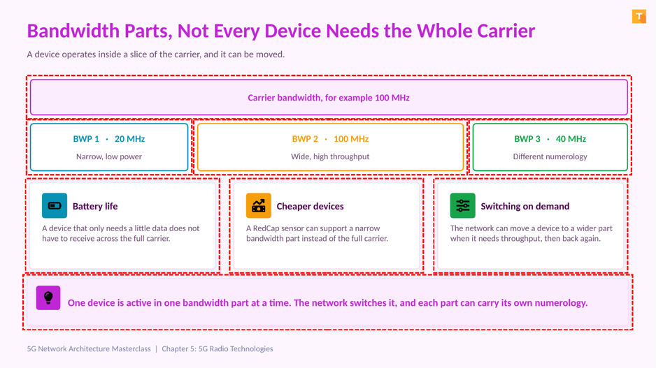
Figure 5.7: A device operates in a slice of the carrier, not all of it.
Bandwidth parts are genuinely new in New Radio and they solve a practical problem. A 5G carrier can be a hundred megahertz wide. Forcing every device to receive across all of it wastes battery and raises device cost, and most devices do not need it.
A bandwidth part is a contiguous subset of the carrier that a device is configured to operate within. Three benefits follow.
Battery life improves, because a device receiving a small amount of data does not have to process the full carrier bandwidth.
Devices get cheaper, which is exactly what Reduced Capability devices from Release 17 depend on. A sensor can support a narrow bandwidth part rather than a hundred megahertz.
The network can switch a device to a wider bandwidth part when it needs throughput, then move it back afterwards to save power.
Remember Two details matter. A device is active in one bandwidth part at a time in a given cell, and each bandwidth part can carry its own numerology. |
5.8 Carrier Aggregation and Dual Connectivity

Figure 5.8: Two ways to give a device more spectrum.
Both mechanisms give a device more spectrum, and they are confused constantly. The distinction is simple once you know what to count.
Question | Carrier Aggregation | Dual Connectivity |
How many nodes serve the device? | One | Two, a master and a secondary |
How many schedulers? | One MAC scheduler | One per node |
What coordinates them? | Internal to the node | The Xn interface, from Chapter 4 |
Typical use | More bandwidth from one site | Combining LTE and NR, or two NR nodes |
Where you have met it | LTE-Advanced onwards | Non Standalone 5G, from Chapter 3 |
Count the nodes and count the schedulers. One of each means carrier aggregation. Two of each means dual connectivity. That test resolves almost every real case.
5.9 Dynamic Spectrum Sharing

Figure 5.9: LTE and New Radio on the same carrier, at the same time.
DSS addresses a migration problem rather than a performance one. An operator holds one band, still has a large LTE device base, and wants to offer 5G coverage in that same spectrum. Refarming the whole band would break LTE service. Splitting it permanently wastes capacity whenever one side is quiet.
How the sharing works
The scheduler allocates resources between LTE and New Radio on a per slot basis, following actual demand rather than a fixed split. As the device base migrates, the balance shifts towards New Radio without manual reconfiguration.
The constraint that creates the complexity
LTE transmits cell specific reference signals at fixed positions in the resource grid, and those cannot be moved. New Radio therefore has to schedule around them, which is the main source of implementation difficulty and of the efficiency loss.
Important Sharing costs efficiency on both sides, because neither technology gets a clean carrier. DSS buys 5G coverage quickly during migration, and most operators retire it once enough devices have moved across. |
5.10 LTE Radio Compared With 5G New Radio

Figure 5.10: Same waveform family, far more flexibility.
Aspect | LTE radio | 5G New Radio |
Subcarrier spacing | Fixed at 15 kHz | 15, 30, 60 or 120 kHz by numerology |
Slot length | Fixed at 1 ms | From 1 ms down to 0.125 ms |
Scheduling start | On the slot boundary | Mini slots can start mid slot |
Channel bandwidth | Up to 20 MHz per carrier | Up to 100 MHz in FR1, 400 MHz in FR2 |
Device bandwidth | The full carrier | A configurable bandwidth part |
Antenna scale | Typically 2 to 8 elements | Commonly 64 elements or more |
Beamforming | Limited and mostly static | Central to the design, mandatory in FR2 |
Always on signals | Cell specific reference signals | Minimised, which improves energy efficiency |
The energy point is easy to miss
LTE transmits cell specific reference signals continuously whether or not anyone is connected. New Radio minimises always on transmission, so a lightly loaded cell can transmit far less. Across a national network that difference is a real operating cost, and it is one reason energy saving features feature so heavily in Release 18.
Key Takeaway Read the table again and one pattern emerges. Every row is the same idea. LTE fixed a parameter, and New Radio made it configurable. |
5.11 What Goes Wrong on the Air Interface

Figure 5.11: Four radio problems and where to look first.
Symptom | Likely cause | What to check |
Coverage shrinks after a numerology change | A higher numerology shortens the cyclic prefix, reducing delay spread tolerance | That the numerology suits the cell radius and the environment |
Millimetre wave drops when the user turns | Beam misalignment, or blockage by a body or a wall | Beam management and the measurement reporting configuration |
Throughput below expectation on massive MIMO | Poor channel state information, so the array cannot form good beams | CSI reporting configuration and sounding reference signal settings |
Both LTE and 5G slower after enabling DSS | Expected behaviour, since neither technology gets a clean carrier | The pre DSS baseline, to confirm this is the trade off rather than a fault |
Did You Know? The fourth row is worth remembering because it prevents wasted escalations. A performance drop after enabling DSS is usually the expected cost of sharing, not a configuration error. |
5.12 Key Takeaways

Figure 5.12: The five points to carry forward.
Numerology is the key idea. Spacing doubles, slot halves, and shorter slots are how URLLC meets its budget.
The frame never changed. Ten millisecond frames and one millisecond subframes, with only the slots inside getting shorter.
Massive MIMO and beamforming differ. One is how many elements you have, the other is what you do with them.
Bandwidth parts save power and reduce device cost by letting a device use a slice of the carrier.
Flexibility is the theme. Every parameter LTE fixed became configurable in New Radio.
Chapter 6 covers spectrum bands in detail, sub 6 gigahertz against millimetre wave, and the Open RAN architecture including the RIC controllers.
Frequently Asked Questions
Is 5G New Radio a completely different waveform from LTE?
No. Both use OFDM, and the downlink in both is cyclic prefix OFDM. If you understand how LTE spreads data across narrow subcarriers, you already understand the foundation. What changed is that parameters LTE fixed, such as subcarrier spacing, became configurable in New Radio.
What does the mu in numerology actually mean?
It is simply an index. Subcarrier spacing equals fifteen kilohertz multiplied by two to the power mu. So mu zero gives fifteen kilohertz, mu one gives thirty, mu two gives sixty and mu three gives one hundred and twenty. The index is a shorthand rather than a physical quantity.
Does a higher numerology always mean better performance?
No, and this is a common assumption. Higher numerology gives shorter slots and therefore lower latency, but it also shortens the cyclic prefix, which reduces tolerance of delay spread and therefore reduces range. It is a trade off chosen to suit the deployment.
Why does millimetre wave need beamforming?
Because path loss at those frequencies is severe and blockage by walls, vehicles and even human bodies is significant. Beamforming concentrates the transmitted energy into a narrow beam aimed at the user, which is what makes the link budget work at all.
How exactly does a shorter slot reduce latency?
A device waits for a transmission opportunity. If slots are one millisecond long, the average wait is longer than if slots are a quarter of a millisecond. Shortening the slot shortens both the waiting time and the transmission time, and mini slot scheduling shortens it further by allowing a start mid slot.
What is the difference between CP-OFDM and DFT-s-OFDM?
Both are OFDM based. DFT spread OFDM applies an additional transform that reduces the peak to average power ratio, which lets the device power amplifier operate more efficiently. It is used on the uplink when the device is power limited, typically at the cell edge.
Can different bandwidth parts use different numerologies?
Yes, and that is one of the reasons the concept exists. One bandwidth part can be configured for a low latency service with wider subcarrier spacing while another serves normal broadband traffic, on the same carrier.
Is multi user MIMO the same as spatial multiplexing?
They are related but distinct. Spatial multiplexing sends multiple streams to one user using different spatial paths. Multi user MIMO sends streams to several different users on the same time and frequency resources. The second is where most of the cell capacity gain comes from.
Why does the frame remain ten milliseconds when everything else became flexible?
Stability at the frame level keeps timing, synchronisation and LTE interworking manageable. If the frame duration itself varied, coexistence with LTE and the design of measurement and paging cycles would become far more complicated for very little benefit.
What limits how many users multi user MIMO can serve at once?
Chiefly the quality of channel state information and the spatial separation between users. If two users have similar spatial signatures the array cannot separate them cleanly, so the practical limit is set by the propagation environment as much as by the number of antenna elements.
Why is hybrid beamforming preferred at millimetre wave?
Fully digital beamforming requires a transceiver chain per element, and millimetre wave arrays have very many elements, so the cost and power consumption become prohibitive. Hybrid applies digital processing across groups of analogue subarrays, keeping most of the flexibility at a fraction of the cost.
How does DSS handle the LTE cell specific reference signals?
It schedules around them. Those signals occupy fixed positions in the LTE resource grid and cannot be moved, so New Radio transmissions must avoid those resource elements. This rate matching around fixed positions is the main source of the efficiency loss that DSS incurs.
Scenario-Based Questions
A large rural cell shows poor performance after a numerology increase. What happened?
Almost certainly the cyclic prefix became too short for the delay spread in that environment. Rural cells have long propagation paths and significant delay spread, so they generally need a lower numerology. Revert and confirm coverage before investigating anything else.
An operator wants URLLC on a mid band carrier. Which radio settings matter most?
A higher numerology to shorten slots, mini slot scheduling to avoid waiting for slot boundaries, and a flexible slot format so uplink opportunities arrive quickly. Remember from Chapter 2 that the radio is only part of the budget, and user plane placement matters just as much.
A stadium deployment needs maximum capacity. Which mechanism helps most?
Multi user MIMO with a large array, because the constraint is many users in a small area rather than peak rate to one user. Adding millimetre wave hotspots helps further, but only where beams can reach the users without persistent blockage.
Massive MIMO throughput is well below the vendor figure. Where do you start?
Start with channel state information. The array cannot form good beams without knowing the channel, so check CSI reporting configuration and sounding reference signal settings. Vendor figures also assume favourable spatial separation between users, which a real cell may not provide.
Users complain that 5G drops indoors near a window. What is likely?
If this is millimetre wave, it is probably blockage. A body or a moving object interrupting the line of sight is enough to break an FR2 link, and recovery depends on beam management finding an alternative path. Check the beam failure recovery configuration.
Architecture-Based Questions
Where does the numerology choice actually get configured?
It is part of the cell and bandwidth part configuration in the Distributed Unit, since scheduling and the physical layer live there as covered in Chapter 4. A device learns the numerology of its bandwidth part through RRC configuration.
Does beamforming affect the CU and DU split?
It affects the DU to RU split specifically. Beamforming weights are applied in the lower physical layer, which sits in the Radio Unit, so the Open Fronthaul interface has to carry the information the Radio Unit needs. This is one reason fronthaul bandwidth scales with antenna count.
How do bandwidth parts relate to network slicing?
They are different mechanisms at different layers and should not be conflated. A bandwidth part is a radio configuration controlling how much spectrum a device uses. A network slice is an end to end logical network defined in the core, as covered in Chapter 13. A slice may influence radio configuration, but they are not the same thing.
Standards Referenced in This Chapter
Document | Subject |
3GPP TS 38.211 | NR physical channels and modulation, including numerology and frame structure |
3GPP TS 38.213 | NR physical layer procedures for control, including beam management |
3GPP TS 38.214 | NR physical layer procedures for data, including CSI reporting and MIMO |
3GPP TS 38.104 | NR base station radio transmission and reception, including FR1 and FR2 bands |
3GPP TS 38.331 | NR Radio Resource Control, including bandwidth part configuration |
3GPP Release 17 | Introduces Reduced Capability devices, which depend on narrow bandwidth parts |
The full 3GPP specification archive is available at 3gpp.org specifications. Always check the release version that matches your deployment.
End of Chapter 5. 5G Radio Technologies
5G Network Architecture Masterclass.
------------------------
Learn Telecom. Crack Interviews. Build Careers.
support@telecomhunt.com | (c) 2026 Telecom Hunt, All rights reserved.


Comments