Chapter 4. NG-RAN Architecture

Updated: 3 days ago


Figure 4.0: Chapter opening. One base station, three separable units.
NG-RAN Architecture
Why 5G took the base station apart, which functions run in the Central Unit, Distributed Unit and Radio Unit, what the split costs in transport, and how F1, NG and Xn tie the whole radio access network together.
4.1 The Change That Reshaped the Base Station
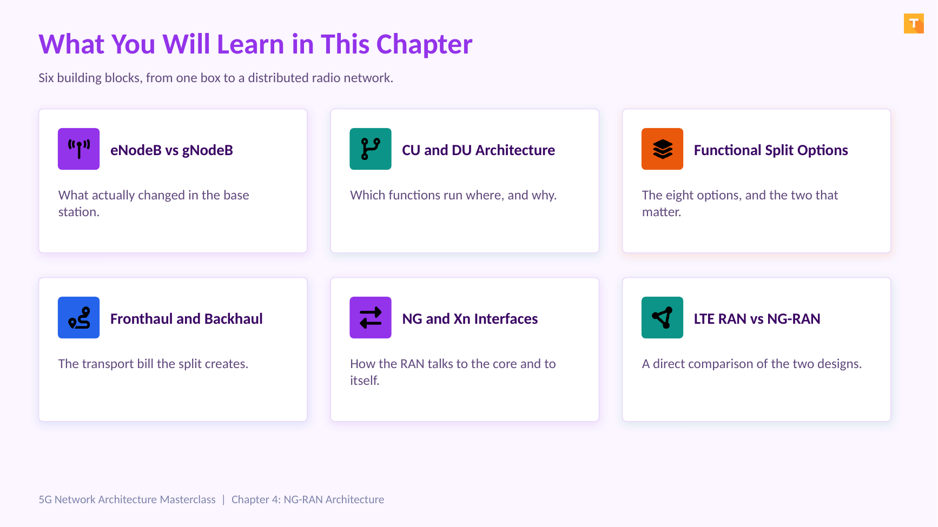
Figure 4.1: The six building blocks of this chapter.
What you will be able to explain by the end
What actually differs between an eNodeB and a gNodeB, beyond the name.
Which protocol layers run in the Central Unit, the Distributed Unit and the Radio Unit.
Why 3GPP studied eight functional splits but the industry deployed only two.
What fronthaul, midhaul and backhaul each demand, and why fronthaul is the expensive one.
What F1, NG and Xn connect, and which of them is not a 3GPP interface.
Remember The gNodeB is a logical node, not a box. One gNodeB is exactly one Central Unit plus one or more Distributed Units, and it still appears to the core network as a single entity. |
4.2 eNodeB and gNodeB Compared

Figure 4.2: One integrated unit becomes one logical node that can be split.
Start with what is genuinely the same. Both nodes terminate the air interface, schedule radio resources, and connect to a core network. The radio protocol layers themselves barely changed between LTE and 5G.
What the eNodeB looks like inside
The eNodeB holds everything in one physical unit at the site. Radio Resource Control and PDCP sit at the top, then RLC and MAC, then the physical layer and the radio front end. One box, one location and, in practice, one vendor.
How the gNodeB is defined instead
The gNodeB is defined in 3GPP TS 38.401 as a logical node that can be realised in separate parts. The Central Unit hosts Radio Resource Control, the Service Data Adaptation Protocol and PDCP. The Distributed Unit hosts RLC, MAC and the higher physical layer functions. The Radio Unit handles the lower physical layer and the radio front end.
Unit | Hosts | Typically located |
Central Unit, CU | RRC, SDAP, PDCP | A hub site or edge data centre serving many sites |
Distributed Unit, DU | RLC, MAC, high PHY | The cell site, or a nearby aggregation point |
Radio Unit, RU | Low PHY, radio front end | At the antenna, on the tower or building |
Specification reference: 3GPP TS 38.401, NG-RAN architecture description
Did You Know? The Service Data Adaptation Protocol, SDAP, is new in 5G. It sits above PDCP and maps QoS flows onto radio bearers, which follows directly from the QoS model change covered in Chapter 10. |
4.3 Where Each Unit Physically Sits

Figure 4.3: The same logical gNodeB, deployed three different ways.
The split is optional. The same logical gNodeB can be deployed three ways, and the choice drives the transport bill more than anything else in this chapter.
Deployment | What sits at the site | Transport needed | Main benefit |
Traditional | CU, DU and RU together | Backhaul only | Simplest to deploy and operate |
Centralised | DU and RU, with the CU at a hub | Mid-haul plus backhaul | Better mobility and dual connectivity coordination |
Fully distributed | RU alone | Fronthaul, mid-haul and backhaul | Greatest pooling gain, simplest site |
Why centralisation helps mobility
When Radio Resource Control decisions for many cells are made in one Central Unit, the decision maker can see all the cells involved in a handover or a dual connectivity setup. That improves coordination in a way a site by site design cannot match.
Important Centralising units saves on site cost and improves coordination, but every unit you move away from the site has to be paid for in fibre. That trade off decides most real deployments. |
4.4 Functional Splits, and Why Only Two Matter

Figure 4.4: The protocol stack, and the two cut points that reached deployment.
3GPP studied eight possible split points in Technical Report 38.801. Reading the stack from the top, each option cuts at a different layer boundary, and each cut produces a different transport requirement. Only two options matter commercially.
Option 2, the CU to DU split
Option 2 cuts between PDCP and RLC, and it became the Central Unit to Distributed Unit split carried over the F1 interface. Everything above the cut is user data at close to its normal rate, so the link is affordable and the latency budget is measured in milliseconds. This is the split most engineers will meet.
Option 7, the DU to RU split
Option 7 cuts inside the physical layer and became the Distributed Unit to Radio Unit split used by the O-RAN Alliance fronthaul specification. Below this cut the link no longer carries user data, it carries sampled radio data, so bandwidth is enormous and the latency budget is measured in tens of microseconds.
| Option 2 | Option 7 |
Cuts between | PDCP and RLC | Layers inside the physical layer |
Becomes | The CU to DU split | The DU to RU split |
Interface | F1, specified by 3GPP | Open Fronthaul, specified by the O-RAN Alliance |
Transport segment | Midhaul | Fronthaul |
Latency budget | A few milliseconds | Around 100 microseconds |
Bandwidth | Close to the user data rate | Very high and nearly constant |
Key Takeaway The rule is simple. Cut higher in the stack and transport is cheap. Cut lower and coordination improves. Everything else is detail. |
4.5 Fronthaul, Midhaul and Backhaul

Figure 4.5: Three transport segments with three very different requirements.
Transport is where split decisions become expensive, and the three segments are not interchangeable.
Segment | Connects | Latency budget | Bandwidth character |
Fronthaul | RU to DU, using eCPRI | Around 100 microseconds | Very high, nearly constant regardless of traffic |
Midhaul | DU to CU, over F1 | A few milliseconds | Close to the actual user data rate |
Backhaul | CU to the 5G Core, over NG | Tens of milliseconds | Scales with real traffic |
Why fronthaul bandwidth does not fall when the cell is quiet
This surprises people the first time they see it. Fronthaul carries sampled radio data rather than user packets, so its bandwidth depends on antenna count, channel bandwidth and sampling, not on how many subscribers are active. An idle cell still consumes nearly the same fronthaul capacity as a busy one.
The tight latency budget has a specific cause too. Hybrid ARQ timing depends on the round trip between the Distributed Unit and the Radio Unit, so exceeding the budget does not degrade performance gracefully, it breaks the radio scheduling loop.
Important Fronthaul normally requires dedicated fibre or a dedicated wavelength. That cost is the main reason full centralisation stays concentrated in dense urban areas where fibre already exists. |
4.6 The NG Interface, RAN to Core

Figure 4.6: NG splits into a control plane path and a user plane path.
The NG interface connects the NG-RAN to the 5G Core and is specified in TS 38.410. It has two parts, and the naming trips people up because the RAN and core specifications use different labels for the same links.
Path | RAN name | Core name | Goes to | Carries |
Control plane | NG-C | N2 | AMF | NGAP over SCTP |
User plane | NG-U | N3 | UPF | GTP-U over UDP |
If that structure feels familiar it should. S1AP over SCTP and GTP-U over UDP did the same jobs in LTE. The transport principles carried across almost unchanged, which is why an LTE transport engineer is already most of the way to understanding NG.
One gNodeB, several AMFs
NG supports a gNodeB connecting to multiple AMFs in a pool, providing resilience and load sharing. Engineers who worked with S1-flex in LTE will recognise the pattern immediately.
Specification reference: 3GPP TS 38.410, NG general aspects and principles
4.7 The Xn Interface, RAN to RAN

Figure 4.7: Neighbouring gNodeBs cooperate directly, without the core.
Xn connects neighbouring NG-RAN nodes directly and is specified in TS 38.420. Its whole purpose is to let neighbours handle routine cooperation without involving the core network.
Xn handover. The two nodes move the UE between themselves and inform the AMF afterwards through a path switch, which is faster than routing every handover through the core.
Dual connectivity coordination. One node acts as master and the other as secondary, which is exactly the mechanism Non Standalone relies on, as covered in Chapter 3.
Load and interference information. Nodes exchange resource status so their schedulers cooperate rather than compete at the cell edge.
Remember Xn is the 5G equivalent of X2 in LTE. Same purpose, updated protocol as XnAP, and the same operational benefit of keeping routine mobility off the core. |
4.8 Every Interface in One Picture

Figure 4.8: The complete NG-RAN interface map.
These three names appear constantly in NG-RAN documentation and get mixed up just as constantly. Learn them together.
Interface | Connects | Carries | Specified by |
NR-Uu | UE to the gNodeB | The New Radio air interface | 3GPP |
Open Fronthaul | RU to DU | Sampled radio data using eCPRI | O-RAN Alliance |
F1 | DU to CU | F1AP signalling and PDCP user data | 3GPP TS 38.470 |
NG | gNodeB to the 5G Core | NGAP to the AMF, GTP-U to the UPF | 3GPP TS 38.410 |
Xn | gNodeB to gNodeB | XnAP for handover and dual connectivity | 3GPP TS 38.420 |
Common Misconception Open Fronthaul is the one interface on this list that is not a 3GPP specification. It comes from the O-RAN Alliance, and that distinction matters when you are reading standards or discussing multi vendor interoperability. |
4.9 Why Split the Base Station at All?

Figure 4.9: Four benefits that justify the extra transport cost.
Having taken the base station apart, it is fair to ask what the industry bought with that complexity. Four things.
Pooling and efficiency. One Central Unit serves many Distributed Units, so baseband capacity is shared rather than provisioned for peak at every site, where busy hours arrive at different times.
Better mobility handling. Radio Resource Control decisions for many cells are made in one place, improving handover and dual connectivity coordination.
Cheaper, simpler sites. Less equipment at the tower means lower power draw, less space and easier maintenance, multiplied across thousands of sites.
Vendor flexibility. Open interfaces between units allow different suppliers for the radio and the baseband, which is the foundation of Open RAN, covered in Chapter 6.
Important None of this is free. Every benefit above is paid for in fibre, timing accuracy and integration effort across more vendors. That is why many operators still deploy traditional integrated sites outside dense areas. |
4.10 LTE RAN Compared With NG-RAN

Figure 4.10: Same job, very different structure.
Aspect | LTE RAN | NG-RAN |
Base station | eNodeB, one integrated unit | gNodeB, a logical node that can be split |
Internal interfaces | None, the stack is internal | F1 between CU and DU, Open Fronthaul to the RU |
Interface to the core | S1-MME and S1-U | NG-C to the AMF, NG-U to the UPF |
Interface between nodes | X2 | Xn |
Protocol layers | RRC, PDCP, RLC, MAC, PHY | Adds SDAP above PDCP for QoS flow mapping |
Transport segments | Backhaul, sometimes fronthaul with CPRI | Fronthaul, midhaul and backhaul |
Vendor model | Normally one vendor per site | Open interfaces allow mixed suppliers |
Key Takeaway The radio protocol layers barely changed. What changed is where they run and who supplies them. Hold that sentence and the whole chapter fits together. |
4.11 What Goes Wrong in a Split RAN

Figure 4.11: Four failures that only exist once the units are separated.
Splitting the base station creates failure modes that simply did not exist when everything sat in one box.
Symptom | Likely cause | What to check |
Cells drop when fronthaul jitters | Fronthaul latency exceeded its budget, breaking hybrid ARQ timing | Fibre path length, switch buffering, whether fronthaul shares transport |
Random throughput loss across a cluster | Timing and synchronisation drift between the RU and the DU | The timing source and Precision Time Protocol distribution |
One vendor blames another | An Open Fronthaul profile mismatch between RU and DU suppliers | That both sides implement the same O-RAN profile and parameter set |
Handovers fail between certain sites only | Xn missing or misconfigured for that specific pair | The Xn setup procedure and neighbour relations for that pair |
Did You Know? Fronthaul should not share transport with other traffic. A shared path introduces jitter that a hybrid ARQ timing loop cannot tolerate, and the symptom appears as unexplained cell drops rather than as a transport alarm. |
4.12 Key Takeaways

Figure 4.12: The five points to carry forward.
The gNodeB is a logical node. One CU plus one or more DUs, appearing to the core as a single entity.
Of eight studied split options, two matter. Option 2 became the CU to DU split, Option 7 the DU to RU split.
Splits are paid for in fibre. Fronthaul needs roughly 100 microseconds and near constant bandwidth.
Three interfaces carry the architecture. F1 inside the gNodeB, NG to the core, Xn between gNodeBs.
The radio protocol layers barely changed. What changed is where they run and who supplies them.
Chapter 5 goes inside the air interface itself, covering numerology, frame structure, massive MIMO and beamforming.
4.13 Frequently Asked Questions
Is a gNodeB a piece of equipment I can point at?
Not necessarily. The gNodeB is a logical node. It may be one physical box at a site, or a Central Unit in a data centre plus several Distributed Units at different sites. What makes it one gNodeB is that it presents itself to the core network as a single entity.
Does every 5G site have to use the CU and DU split?
No. The split is optional. Many operators deploy traditional integrated sites where the Central Unit, Distributed Unit and Radio Unit sit together, which looks much like an LTE site and needs only backhaul. The split is chosen where its benefits justify the transport cost.
What is the difference between a Radio Unit and an antenna?
The antenna radiates the signal. The Radio Unit contains the radio front end and the lower physical layer processing, including functions such as the fast Fourier transform and beamforming. In many modern products the two are integrated into a single active antenna unit.
Why is it called fronthaul rather than just backhaul?
Backhaul traditionally means the link from the site to the core. Fronthaul names the link that sits in front of the baseband, between the radio and the processing. Midhaul was then added for the link between the Distributed Unit and the Central Unit, giving three named segments.
Why does fronthaul bandwidth stay high when the cell is idle?
Because fronthaul carries sampled radio data rather than user packets. Its bandwidth depends on antenna count, channel bandwidth and sampling rate, none of which change with subscriber activity. An idle cell consumes nearly the same fronthaul capacity as a busy one.
Why is the fronthaul latency budget so tight?
Hybrid ARQ timing depends on the round trip between the Distributed Unit and the Radio Unit. If that budget is exceeded the retransmission timing breaks, so performance does not degrade gracefully. This is why roughly 100 microseconds is treated as a hard constraint rather than a target.
What exactly does F1 carry?
F1 carries two things. F1AP signalling between the Central Unit and Distributed Unit for procedures such as UE context setup, and PDCP level user data. It is specified in TS 38.470 and its associated series, and it corresponds to functional split Option 2.
Can one Central Unit serve Distributed Units from another vendor?
In principle F1 is a 3GPP specified interface, so it should interoperate. In practice most operators deploy CU and DU from the same vendor, while multi vendor separation happens more often at the Open Fronthaul interface between the Distributed Unit and the Radio Unit.
Why did the industry converge on Options 2 and 7 rather than the others?
They sit at the two useful extremes. Option 2 gives most of the centralisation benefit at an affordable transport cost, because the link still carries user data. Option 7 keeps the Radio Unit simple and cheap, enabling multi vendor radio, at the price of demanding fronthaul. The intermediate options offered less benefit for comparable complexity.
What is the relationship between CU-CP and CU-UP?
The Central Unit can itself be divided into a control plane part hosting RRC and the PDCP control plane, and one or more user plane parts hosting the PDCP user plane and SDAP. They are joined by the E1 interface. This allows control and user plane processing to scale independently, echoing the CUPS principle from the core network.
How is timing distributed in a split RAN?
Through Precision Time Protocol, commonly with a GNSS derived reference. Every element in the fronthaul path must maintain accurate phase alignment, since time division duplex operation and beamforming both depend on it. Timing distribution becomes a first class design problem once the Radio Unit is separated from the Distributed Unit.
Does the split affect how the core network sees the RAN?
No, and that is deliberate. The core communicates with the gNodeB over NG regardless of how the gNodeB is internally divided. The AMF does not know or care whether there is one Distributed Unit or twenty behind the Central Unit.
Scenario-Based Questions
An operator wants to centralise baseband across forty sites. What decides feasibility?
Fibre availability and path length. Centralising the Distributed Unit requires fronthaul with roughly 100 microseconds of budget and near constant high bandwidth, which normally means dedicated fibre or a dedicated wavelength per site. If that fibre does not exist, centralising the Central Unit only, using midhaul, is usually the realistic compromise.
A vendor proposes Open RAN with separate RU and DU suppliers. What should you verify first?
That both suppliers implement the same Open Fronthaul profile and parameter set. The specification allows options, and mismatched options are the most common source of multi vendor integration failure. Agree the profile in writing before procurement rather than during integration testing.
Why might an operator keep traditional integrated sites in rural areas?
Because the benefits of splitting scale with density. Pooling gains require many sites sharing a hub, and fronthaul requires fibre that rural sites often lack. An integrated site needing only backhaul is usually both cheaper and more robust in that setting.
Troubleshooting Based Question
Throughput drops across an entire cluster at the same moment. Where do you look first?
A cluster wide simultaneous event points at something shared. Check the timing source and Precision Time Protocol distribution, and then the shared transport path. A single cell problem looks different, since it affects one site rather than everything served by the same hub.
Handovers fail between two specific gNodeBs but work elsewhere. What is wrong?
That pattern points at Xn rather than at radio conditions. Check whether the Xn interface was set up between those two nodes and whether the neighbour relation exists on both sides. A missing Xn forces the handover through the core or fails it outright.
Architecture-Based Question
Where does SDAP sit and why was it added?
SDAP sits above PDCP in the Central Unit and maps QoS flows onto radio bearers. It exists because 5G replaced the LTE bearer model with QoS flows inside a PDU session, so something had to translate between the core network view and the radio bearer view. Chapter 10 covers the QoS model in full.
How does the CU and DU split relate to Open RAN?
They are related but not the same. The CU and DU split is a 3GPP concept defined by functional split Option 2 and the F1 interface. Open RAN, defined by the O-RAN Alliance, adds the open interface between the Distributed Unit and the Radio Unit plus the RIC controllers. Chapter 6 covers Open RAN properly.
If the gNodeB is split, which part connects to the core?
The Central Unit. It terminates NG-C towards the AMF and NG-U towards the UPF. The Distributed Unit connects only to its Central Unit over F1, and the Radio Unit connects only to its Distributed Unit over Open Fronthaul.
Standards Referenced in This Chapter
Document | Subject |
3GPP TS 38.401 | NG-RAN architecture description, including the CU and DU split |
3GPP TR 38.801 | Study on new radio access technology, including the eight functional split options |
3GPP TS 38.410 | NG general aspects and principles, the interface to the 5G Core |
3GPP TS 38.420 | Xn general aspects and principles, the interface between gNodeBs |
3GPP TS 38.470 | F1 general aspects and principles, the interface between CU and DU |
O-RAN Alliance | Open Fronthaul specification, the interface between DU and RU |
The full 3GPP specification archive is available at 3gpp.org specifications. Always check the release version that matches your deployment.
End of Chapter 4. NG-RAN Architecture
5G Network Architecture Masterclass.
------------------------
Learn Telecom. Crack Interviews. Build Careers.
support@telecomhunt.com | (c) 2026 Telecom Hunt, All rights reserved.


Comments