Chapter 1. Evolution of Mobile Networks ( 2G to 5G )

Updated: 3 days ago
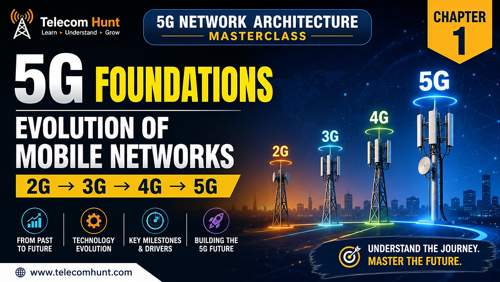


Figure 1.0: Chapter opening. Five generations, one continuous engineering story.
Chapter 1. Evolution of Mobile Networks ( 2G to 5G )
1.1 Why This Chapter Comes First

Figure 1.1: The six building blocks of this chapter, arranged problem first and answer second.
Most 5G courses open with a list of features. Twenty gigabits per second. One millisecond latency. A million devices per square kilometre. Those numbers are real, but they explain nothing on their own. They tell you what 5G achieves without telling you why the network had to be rebuilt to achieve it.
This chapter takes the opposite route. We study the problem before the answer. By the time the 5G System appears in section 1.9, every part of it will look like a direct response to something you already saw failing in the 4G design.
What you will be able to learn in Chapter 1. Evolution of Mobile Networks ( 2G to 5G )
How the radio and the core network changed across five generations, and what each change was for.
Why operators rebuild the network roughly every ten years, and why economics matters more than speed.
Where the LTE architecture hits structural walls that no software patch can move.
Which enterprise requirements a consumer grade network was never designed to meet.
The six design ideas behind the 5G System, and the 3GPP specifications that define them.
Remember Every 5G design choice answers a 4G limitation. If you can name the limitation, you will never forget the answer. |
1.2 One Network, Five Generations

Figure 1.2: The generational timeline from 1G analog voice through to 5G New Radio and the 5G Core.
Look at the timeline above and notice what it is not. It is not a speed chart. Each milestone marks a change in what the network could carry, and the speed increase was a consequence of that change rather than the goal of it.
1G: proving that people wanted mobility
The first generation used analog radio and carried voice only. There was no SMS, no data, and no encryption worth the name, so anyone with a suitable receiver could listen to a call. Capacity was tiny and handsets were heavy. What 1G did prove, decisively, was that people would pay for mobility.
2G: voice goes digital, and an accident changes everything
GSM arrived commercially in 1991 and digitised the air interface. Digital coding brought encryption, far better spectral efficiency and enough capacity to serve mass markets. The SIM card separated identity from hardware, which is what made international roaming practical.
SMS was designed as a minor signalling side feature. It became one of the most profitable services in telecom history. Later, GPRS and EDGE bolted packet data onto a network built for circuits, reaching roughly 384 kilobits per second at best.
Did You Know? The SIM card is the reason your phone number is not tied to your handset. That single design decision separated subscriber identity from device identity, and 5G still follows the same principle with the SUPI and the USIM. |
3G: the core network finally takes data seriously
UMTS arrived from 2001 and introduced a packet switched domain alongside the circuit domain. For the first time, data was not an afterthought riding on voice infrastructure. HSPA and HSPA Plus pushed throughput towards 42 megabits per second, and the mobile internet stopped being a demonstration and started being a product.
4G: the structural break
LTE, standardised in 3GPP Release 8 and deployed from 2009, made the largest structural change in mobile history. It removed the circuit switched domain completely. Everything became IP, including voice, which returned as VoLTE riding on the IP Multimedia Subsystem. The architecture flattened, the radio used OFDMA, and video streaming became the default behaviour of a mobile network.
5G: from one customer type to many
5G New Radio began commercial rollout in 2018, built to the IMT-2020 requirements and specified from 3GPP Release 15 onwards. The headline rates matter less than the change in scope. 5G is the first generation designed from the start to serve smartphones, factory robots, vehicles and metering fleets on the same infrastructure, with different guarantees for each.
Specification reference: ITU-R Recommendation M.2083, IMT Vision for 2020 and beyond. This document defines the eMBB, URLLC and mMTC service classes that shape the whole 5G design.
Key Takeaway No generation discarded the previous promise. Each one kept it and added a new capability class on top. That is why an LTE engineer is already most of the way to being a 5G engineer. |
1.3 What Each Generation Was Actually Built to Solve

Figure 1.3: Three eras of mobile networking, and the very different question each one answered.
Grouping five generations into three eras makes the pattern easier to hold. Each era asked the network a different question, and the architecture reshaped itself to answer it.
Generation | Problem it solved | Enabling technology | Peak data rate | Core network |
1G | Mobility for voice | Analog FM radio | Voice only, about 2.4 kbps | Analog switching |
2G | Capacity and privacy | Digital TDMA, GSM, SIM | 9.6 kbps, GPRS to 384 kbps | Circuit switched, GPRS added later |
3G | Usable mobile data | WCDMA, HSPA | 384 kbps to 42 Mbps | Circuit domain plus packet domain |
4G | True mobile broadband | OFDMA, all IP LTE | 100 Mbps to 1 Gbps with LTE-Advanced | EPC, fully packet switched |
5G | Service diversity | New Radio, flexible numerology | Up to 20 Gbps peak target | 5G Core, service based |
Important The peak rates above come from the specifications and describe theoretical maximums under ideal conditions. Real user throughput depends on spectrum, cell load, distance and device category, and is normally a small fraction of the peak. |
Read the last column again. The core network changed shape in every single era, and that is the part of the story most learners skip. The radio gets the marketing attention, but the core is where the business model lives.
1.4 Why Mobile Networks Never Stop Evolving

Figure 1.4: Six forces that push operators into a rebuild roughly every decade.
A network rebuild costs billions and takes years. No operator does it for fun. Six pressures build until the existing architecture can no longer absorb them, and then the industry moves.
Traffic grows faster than capacity
Video dominates mobile data volume and its share keeps climbing. Higher resolutions, longer sessions and more devices per subscriber all compound. Adding spectrum and cells helps, but demand has consistently outpaced the supply of both.
Devices stopped looking like phones
A smartphone sends large bursts and expects high throughput. A water meter sends a few bytes twice a day and expects a ten year battery. A factory sensor sends tiny packets constantly and expects them to arrive on time, every time. One traffic model cannot serve all three efficiently.
Latency became a product requirement
Cloud gaming, remote operation, augmented reality and industrial control all need responses in single digit milliseconds. Latency is partly physics. If the user plane anchor sits hundreds of kilometres away, no amount of radio optimisation will fix the round trip.
Cost per bit decides survival
This is the pressure that engineers underestimate and finance teams never do. Data volume grows steeply while revenue per subscriber stays roughly flat. If the cost of carrying a bit does not fall at least as fast as volume rises, the operator loses money on growth. Every generation has had to move more data for less money per unit.
Spectrum is finite, expensive and regulated
Operators buy spectrum in auctions that can cost more than the network equipment. Once bought, the only way to get more capacity from it is better spectral efficiency, which means new radio technology.
Connectivity alone is a thin margin business
Selling megabytes puts an operator in direct price competition with every other operator. Selling a guaranteed slice to a port operator, or an exposed network capability to an enterprise developer, does not. This search for defensible revenue explains a large part of the 5G feature set.
Common Misconception Operators do not upgrade generations to win speed test screenshots. They upgrade to keep cost per bit falling while demand keeps rising, and to reach revenue that connectivity alone cannot deliver. |
1.5 Inside 4G: How the Evolved Packet Core Works

Figure 1.5: The Evolved Packet System, showing control plane paths in blue and user plane paths in orange.
You cannot fairly criticise the LTE architecture until you can draw it. Study this diagram properly, because every limitation in the next section points at a specific box or line in it.
The access side
The device attaches to the eNodeB over the LTE-Uu air interface. In LTE the eNodeB is one physical unit holding the complete radio protocol stack, from the physical layer up through RRC. That monolithic design is simple to deploy and, as you will see in Chapter 4, is exactly what 5G splits apart.
Where control and data separate
Two paths leave the eNodeB. S1-MME carries signalling to the Mobility Management Entity using S1AP over SCTP. S1-U carries subscriber traffic to the Serving Gateway inside GTP-U tunnels. The split happens at the radio, which is important, because in the core the two planes come back together.
The control plane chain
The MME is the brain of the EPC. It handles attach, authentication, mobility and session signalling. It fetches subscriber data from the Home Subscriber Server over S6a using Diameter, and it instructs the Serving Gateway over S11 using GTP-C. Policy and charging rules come from the PCRF and land at the PDN Gateway over Gx.
The user plane chain
Subscriber traffic flows from the eNodeB to the Serving Gateway, then to the PDN Gateway over S5 for a home subscriber or S8 for a roaming one. The PDN Gateway is the IP anchor point. It assigns the IP address, enforces policy and hands traffic to the internet or an enterprise network over SGi.
Interface | Between | Protocol | Carries |
LTE-Uu | UE and eNodeB | LTE air interface | Radio signalling and user data |
S1-MME | eNodeB and MME | S1AP over SCTP | Control signalling |
S1-U | eNodeB and S-GW | GTP-U | User plane traffic |
S11 | MME and S-GW | GTP-C | Session control |
S6a | MME and HSS | Diameter | Subscriber data and authentication |
S5 and S8 | S-GW and P-GW | GTP-C and GTP-U | Session control and user traffic |
Gx | PCRF and P-GW | Diameter | Policy and charging rules |
SGi | P-GW and data network | IP | Traffic to the internet or enterprise |
Specification reference: 3GPP TS 23.401, General Packet Radio Service enhancements for E-UTRAN access. This is the definitive EPS architecture specification and is worth keeping open while you work.
Remember Count the interfaces in the table above. Every one is a fixed, point to point relationship with its own protocol. Adding a new network function means agreeing a new interface with every function it needs to talk to. |
1.6 Where the LTE Architecture Runs Out of Room

Figure 1.6: Six structural limits of the LTE architecture, each one a deliberate design choice for a different era.
None of the following is a bug. LTE does precisely what it was designed to do. The problem is that the design assumed one kind of customer, a smartphone user consuming best effort broadband, and the market moved somewhere else.
Limitation 1: network functions ship as appliances
EPC nodes began life as purpose built vendor hardware. When you need more capacity, you buy another chassis, ship it, rack it, cable it and integrate it. The lead time is measured in weeks or months, which makes it impossible to follow demand that moves in hours.
Limitation 2: rigid point to point interfaces
Diameter and GTP interfaces are configured peer relationships. Ten functions that all need to talk to each other require a large number of configured links, and the count grows far faster than the number of functions. Adding a capability often means extending a protocol and agreeing that extension across multiple vendors first.
Limitation 3: control and user plane bundled together
In the original Release 8 design, the Serving Gateway and PDN Gateway carry both signalling and subscriber traffic in the same node. If you need more throughput, you also buy control plane capacity you may not need, and the reverse is equally true. 3GPP addressed this in Release 14 with Control and User Plane Separation, but that arrived late in the LTE life cycle and remained optional in many deployments.
Specification reference: 3GPP TS 23.214, Architecture enhancements for control and user plane separation of EPC nodes
Limitation 4: one size fits all traffic treatment
LTE differentiates services using access point names and EPS bearers with QCI values. That mechanism is genuinely useful, but it is coarse. A water meter and a 4K video stream share the same EPC. You can prioritise traffic, but you cannot hand a customer a network with its own isolated resources and its own performance contract.
Limitation 5: centralised gateway anchoring
Most operators deployed a small number of PDN Gateways in central data centres. Traffic from a device therefore travels a long way to reach its anchor, then travels back. Physical distance sets a latency floor that no software optimisation can move.
Limitation 6: new services arrive on the vendor timeline
Because software was tied to specific hardware platforms and release cycles, a new service could take quarters to reach production. Enterprise customers, used to cloud services that change weekly, found that pace difficult to accept.
Important These six limits are the whole reason the 5G Core looks the way it does. Learn them properly and the rest of this course stops feeling like a list of new acronyms. |
1.7 How New Business Needs Changed the Requirements

Figure 1.7: Industries that now buy connectivity, and the requirements they bring with them.
The most important change in 5G is not technical. It is commercial. The buyer is no longer only a consumer choosing a tariff. It is a plant manager, a hospital IT director or a port operations lead, and they arrive with requirements written into contracts.
Sector | What they deploy | What they demand from the network |
Manufacturing | Automated guided vehicles, machine vision, motion control | Deterministic latency, traffic isolation, on premises coverage |
Automotive and transport | Vehicle to everything messaging, assisted driving, fleet telemetry | Low latency at high mobility, fast handover, wide area consistency |
Healthcare | Connected imaging, patient telemetry, remote diagnostics | Very high availability, predictable performance, control over data location |
Energy and utilities | Smart metering, grid protection, remote substations | Massive device density, long battery life, strong reliability |
Media and entertainment | Live production, remote cameras, immersive video | Sustained uplink bandwidth, low jitter, scheduled capacity |
Ports and logistics | Remote crane control, autonomous yard vehicles, asset tracking | Reliability, isolation, dense coverage in a small area |
The requirement that breaks the old model
Read the third column again and one word keeps appearing: isolation. A manufacturer does not want priority over consumer traffic, because priority is a relative promise that changes with load. They want their own network behaviour, unaffected by whatever else is happening in the cell.
LTE cannot offer that in any meaningful sense. Bearers and access point names differentiate traffic within one shared system, and under heavy load the differentiation degrades for everyone. This single requirement is what makes network slicing a core feature of 5G rather than an optional extra.
Key Takeaway Enterprises moved latency, reliability, device density and isolation from optional extras to contractual obligations. A best effort pipe cannot sign that contract. |
1.8 The Six Ideas Behind the 5G System

Figure 1.8: Six design principles of the 5G System, each answering a specific LTE limitation.
The 5G System is not a collection of new acronyms. It is six design decisions, and each one maps directly onto a limitation from section 1.6.
5G design idea | What it changes | LTE limitation it answers |
Service Based Architecture | Network functions publish services and call each other over HTTP/2 REST APIs, discovering peers through the NRF | Rigid point to point interfaces |
Control and user plane separation | The UPF forwards packets while the AMF and SMF handle control, each scaling on its own | Bundled planes in the gateways |
Cloud native by design | Functions run as containers on common hardware, deployed through automated pipelines | Appliance based network nodes |
Native network slicing | One infrastructure carries many logical networks, each identified by an S-NSSAI | One size fits all traffic treatment |
Edge ready user plane | The UPF can sit inside a factory, a stadium or a city site, close to the data | Centralised gateway anchoring |
Open network exposure | The NEF and standard APIs let enterprises consume network capability directly | Slow, closed service creation |
Why service based architecture matters more than it sounds
In the EPC, if function A needs something from function B, engineers define an interface, choose a protocol, extend it if needed and configure the peer relationship at both ends. In the 5G Core, function B registers its services with the Network Repository Function, and function A discovers and calls them over HTTP/2. This is how ordinary web systems have worked for years, and bringing it into the core is what allows new functions to appear without a new interface.
Why separating the user plane changes the economics
Once the UPF is an independent function, throughput capacity and signalling capacity become separate purchases. An operator can scale packet forwarding for a stadium event without touching registration capacity, and can place forwarding capacity geographically wherever latency demands it.
Specification reference: 3GPP TS 23.501, System architecture for the 5G System. Procedures are in TS 23.502 and policy and charging in TS 23.503.
Remember Security is not a seventh idea bolted on the side. It runs through all six, including the concealed subscriber identity that stops the permanent identifier from ever crossing the radio in the clear. |
1.9 How the 5G System Puts the Philosophy Into Practice

Figure 1.9: The 5G System architecture. Control plane functions sit on a service based bus while the user plane runs straight through.
Compare this diagram with Figure 1.5 and the transformation becomes concrete. The same jobs still exist. What changed is how the functions connect, scale and deploy.
The access and user plane path
The device attaches to the gNodeB over the New Radio air interface. N2 carries signalling to the Access and Mobility Management Function, and N3 carries subscriber traffic to the User Plane Function. Notice that user traffic never touches a control plane node. N6 takes it out to the data network, and N9 connects UPFs to each other when traffic needs more than one hop.
The control plane and the service bus
The AMF handles registration, connection and mobility. It asks the Session Management Function to establish sessions, and the SMF programs the UPF over N4. Above them, the AUSF, UDM, PCF, NRF and NSSF expose their services on the service based interface bus. Any authorised function can call any other, which is what makes the architecture extensible.
Mapping the old world onto the new
EPC function | 5G Core equivalent | What actually changed |
MME | AMF plus SMF | Mobility and session control split into two independently scalable functions |
S-GW and P-GW | UPF | One user plane function, deployable centrally or at the edge |
HSS | UDM with UDR | Subscriber logic separated from subscriber data storage |
PCRF | PCF | Policy moved onto the service based interface with API access |
HSS authentication | AUSF | Authentication became its own service |
No equivalent | NRF | Service registration and discovery, the heart of the service based design |
No equivalent | NSSF | Slice selection, which had no meaning in the EPC |
No equivalent | NEF | Controlled exposure of network capability to external applications |
Common Misconception A common belief is that 5G deleted the 4G functions and invented new ones. It did not. It split them, gave them APIs, and let each one scale and move independently. |
1.10 4G and 5G Side by Side

Figure 1.10: A row by row comparison of the two architectures.
Use this table as a revision sheet. Each row is a full topic later in the course, and the difference between the two columns is usually the exam question and the design review question at the same time.
Aspect | 4G LTE with EPC | 5G with 5G Core |
Architecture style | Point to point interfaces, Diameter and GTP-C | Service based, HTTP/2 with REST APIs |
Control and user plane | Combined by default, CUPS added in Release 14 | Separated by design from Release 15 |
Mobility and session control | MME handles both | AMF for mobility, SMF for sessions |
User plane gateway | S-GW and P-GW | UPF, placeable at the edge |
Subscriber data and policy | HSS and PCRF | UDM with UDR, and PCF |
Service differentiation | APN and EPS bearers with QCI | Network slicing with S-NSSAI and QoS flows |
Deployment model | Physical or virtual appliances | Cloud native containers with automated delivery |
Typical end to end latency | Around 30 to 50 milliseconds | Around 1 to 10 milliseconds depending on service and placement |
Network exposure | Limited, mostly through SCEF | NEF with standardised APIs for enterprise use |
1.11 From LTE Attach to 5G Registration

Figure 1.11: The same job, done by different functions over different interfaces.
Procedures make architecture real. Put the two sequences next to each other and the split of the MME into AMF and SMF stops being abstract.
LTE Attach, step by step
The UE establishes an RRC connection with the eNodeB.
The Attach Request reaches the MME over S1-MME.
The MME authenticates the UE using subscriber data from the HSS over S6a.
The MME asks the S-GW and P-GW to create the session.
The PCRF installs policy and charging rules at the P-GW over Gx.
The Attach Accept returns to the UE and the default bearer is live.
5G Registration, step by step
The UE establishes an RRC connection with the gNodeB.
The Registration Request reaches the AMF over N2.
The AMF authenticates the UE using the AUSF and the UDM.
The Registration Accept returns to the UE. Registration is complete on its own.
A separate PDU Session Establishment request goes to the SMF.
The SMF programs the UPF over N4 and QoS flows begin carrying traffic.
Important The difference in step four matters. In LTE, attach and default bearer setup are one combined procedure. In 5G, registration and PDU session establishment are separate procedures, so a device can be registered without any active session. That separation is what supports flexible session handling later. |
Troubleshooting the same symptoms in both worlds
Symptom | Where to look in LTE | Where to look in 5G |
Attach or registration rejected | Subscription in HSS, S6a Diameter path, MME logs | Subscription in UDM, AMF to AUSF path, NAS cause code |
Session setup fails | S11 and S5 GTP-C, APN configuration at the P-GW | N11 to SMF, N4 association to the UPF, DNN configuration |
Poor throughput after setup | Bearer QCI mapping, S1-U transport, P-GW placement | QoS flow mapping, N3 transport, UPF placement versus the data network |
Signalling overload during events | MME control capacity, Diameter peer limits | AMF instance scaling, NRF discovery load, service mesh limits |
1.12 Key Takeaways

Figure 1.12: The five points to carry into the rest of the masterclass.
Every generation kept the previous promise and added a new capability class. Voice, then data, then broadband, then service diversity.
Economics drives evolution more than speed does. Operators rebuild to keep cost per bit falling while traffic climbs.
The LTE limits are structural design choices, not defects. Appliance based nodes, rigid interfaces, bundled planes and centralised gateways all made sense for a consumer broadband network.
Enterprises changed the requirement set. Latency, reliability, device density and isolation became contractual rather than optional.
5G split the 4G functions and gave them APIs. The MME became the AMF and SMF, the gateways became the UPF, the HSS became the UDM with the UDR, and the PCRF became the PCF.
Key Takeaway If you remember one sentence from this chapter, make it this one. 5G is not a faster 4G. It is a differently shaped system built for a wider set of customers. |
Next One - Chapter 2 takes the next logical step. It examines the IMT-2020 requirements in detail and the three service categories that define 5G: enhanced mobile broadband, ultra reliable low latency communication, and massive machine type communication.
1.13 Frequently Asked Questions
These are the questions learners ask most often about this chapter, arranged from foundational through to architectural.
Is 5G simply a faster version of 4G?
No. Speed is the most visible change but the least important one. 5G restructured the core network around independent software services, separated the user plane so it can be placed anywhere, and added slicing so different customers get genuinely different network behaviour. A faster 4G would have delivered none of that.
What does the G in 2G, 3G, 4G and 5G actually mean?
It stands for generation. Each generation is a set of standards defined by 3GPP and measured against requirements set by the ITU. A generation change means a new radio interface and normally a new core network architecture, not just an incremental improvement.
Why did voice move onto IP in 4G?
LTE removed the circuit switched domain entirely, so there was no circuit path left to carry a call. Voice returned as VoLTE, which is a service delivered by the IP Multimedia Subsystem over the same packet network that carries data. This simplified the architecture and let one transport carry everything.
Does 5G replace 4G completely?
Not for a long time. Most operators launched 5G in Non Standalone mode, which uses the existing EPC with 5G radio. Even after moving to Standalone 5G, LTE continues to provide coverage and capacity, and the two generations interwork. Chapter 3 covers the deployment options in detail.
What is the practical difference between an EPS bearer and a QoS flow?
An EPS bearer is a tunnel with a fixed QCI, established end to end, and every packet in it receives the same treatment. A QoS flow is finer grained and is identified by a 5QI, with multiple flows mapped into a single PDU session. The 5G model lets the network change treatment for part of a session without rebuilding the whole tunnel.
If CUPS already existed in LTE, what did 5G add?
CUPS was added to the EPC in Release 14 and separated the gateways into control and user parts. 5G made that separation native and universal rather than optional, and combined it with service based interfaces and cloud native deployment. The result is that a UPF can be instantiated, moved and scaled as software, which CUPS alone did not deliver.
Why does the 5G Core use HTTP/2 instead of Diameter?
Diameter interfaces are point to point and require configured peer relationships, so the integration effort grows quickly as functions are added. HTTP/2 with REST APIs allows a function to register its services with the NRF and be discovered at runtime. It also lets operators use mature web tooling for load balancing, observability and security.
What is the relationship between a slice and an APN?
They solve related problems at very different depths. An APN selects a gateway and a set of policies within one shared network. A slice is a logical network with its own selected network functions, its own performance characteristics and its own isolation properties, identified by an S-NSSAI. Chapter 13 covers slicing fully.
Why was the subscriber identity changed from IMSI to SUPI and SUCI?
In LTE the permanent identifier could be sent over the radio in the clear in certain situations, which enabled passive tracking. In 5G the permanent identity is the SUPI, and it is concealed using the home network public key to produce the SUCI before it ever crosses the air interface. Chapter 12 covers the mechanism and Chapter 18 covers the security architecture.
Does a service based architecture add latency compared with Diameter?
There is protocol overhead in HTTP/2 and JSON compared with a binary protocol, and it is measurable. In practice it is small relative to the gains, and it applies only to control signalling. The user plane never touches the service based bus, so subscriber traffic latency is unaffected.
What does stateless actually mean for a 5G network function?
It means the function does not hold session state in its own memory between transactions. State is stored externally, commonly in the UDR or an unstructured data storage function. Any instance can then serve any request, which is what allows instances to be added, removed or restarted without dropping sessions.
Is the 5G Core dependent on Kubernetes?
The 3GPP specifications define functions and interfaces, not the platform they run on. In practice most commercial 5G Core deployments use containers orchestrated by Kubernetes, because the cloud native model assumes horizontal scaling and automated lifecycle management. Chapter 14 covers the platform layer.
Scenario-Based Questions
A manufacturer wants guaranteed performance on its factory floor. Why is LTE a poor fit?
LTE can prioritise their traffic, but prioritisation is relative and degrades under load. It cannot give the customer dedicated network resources with a measurable isolation boundary, and it cannot place the user plane inside the factory to control latency and keep data local. Slicing plus an edge UPF answers all three needs.
A cloud gaming customer reports lag while speed tests look excellent. What is happening?
Throughput and latency are separate problems. The speed test measures how much data flows, while the complaint is about how long the round trip takes. If the user plane anchor sits in a central data centre far from the user, the physical distance sets a latency floor. Moving the UPF closer is the structural fix.
A utility wants to connect a million meters. Which requirements dominate?
Device density, battery life and signalling efficiency, not throughput. Each meter sends very little data, so the design challenge is supporting an enormous number of connections without overwhelming the control plane, and letting devices sleep for long periods. This is the massive machine type communication category, covered in Chapter 2.
Troubleshooting Based Questions
During a large public event, radio counters look healthy but users cannot connect. Where do you look?
Look at the control plane before the radio. Large gatherings produce attach and registration storms, and in LTE the MME can saturate while radio resources are still available. Check signalling load, Diameter peer capacity and any admission control that may be rejecting requests.
After a regional power failure, a large IoT fleet reconnects and the network struggles. Why?
Tens of thousands of devices attempting registration in the same seconds create a signalling burst far beyond normal patterns. In an architecture where control capacity is fixed hardware, the burst simply exceeds it. Horizontal scaling plus back off mechanisms in the devices are the standard mitigations.
Architecture-Based Questions
Why was the MME split into the AMF and SMF?
The MME performed two jobs with very different scaling profiles. Mobility management scales with the number of registered devices and their movement, while session management scales with the number and complexity of sessions. Separating them allows each to be sized and scaled independently, and it lets session control move closer to the user plane it manages.
What exactly does the NRF do, and what happens if it fails?
The Network Repository Function holds the registry of available network function instances and their services, and it answers discovery requests. Because it is central to service discovery, operators deploy it redundantly, and network functions cache discovery results so that an NRF outage degrades new discovery rather than stopping active sessions.
Where does the RAN fit into the service based architecture?
It does not. The service based interfaces apply to the 5G Core control plane only. The NG-RAN connects to the core through N2 to the AMF and N3 to the UPF, both of which are traditional reference point interfaces. Chapter 4 covers the NG-RAN architecture in detail.
Standards Referenced in This Chapter
Document | Subject |
ITU-R M.2083 | IMT Vision for 2020 and beyond, defining eMBB, URLLC and mMTC |
3GPP TR 38.913 | Study on scenarios and requirements for next generation access technologies |
3GPP TS 23.401 | EPS architecture for E-UTRAN access, the definitive LTE core specification |
3GPP TS 23.214 | Control and user plane separation of EPC nodes, introduced in Release 14 |
3GPP TS 23.501 | System architecture for the 5G System |
3GPP TS 23.502 | Procedures for the 5G System, including registration and PDU session establishment |
3GPP TS 23.503 | Policy and charging control framework for the 5G System |
The full 3GPP specification archive is available at 3gpp.org specifications. Always check the release version that matches your deployment.
End of Chapter 1. Evolution of Mobile Networks ( 2G to 5G ).
5G Network Architecture Masterclass
------------------------
Learn Telecom. Crack Interviews. Build Careers.
support@telecomhunt.com | (c) 2026 Telecom Hunt, All rights reserved.


Comments